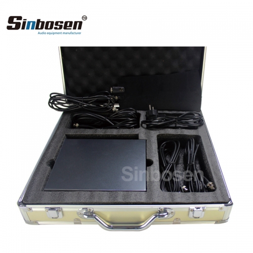
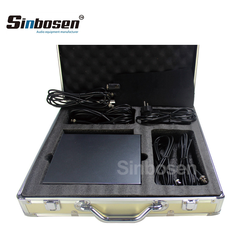
Antenna Amplifier
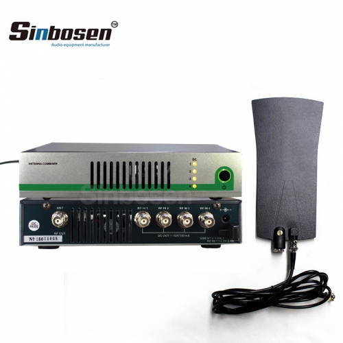
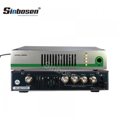
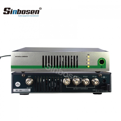
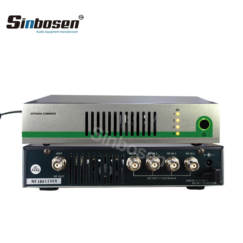
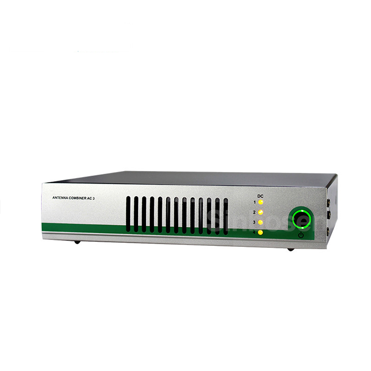
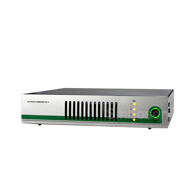
Sinbosen professional antenna distribution system monitor in ear monitor AC-3
Item No.: AC-3
Brand: Sinbosen
Model: AC-3
Communication: Wireless
Frequency Range: 490-900MHz
Impedance:50 Ohm
Transmission loss:0dB ± 1dB
Warranty: 2 Years
Terms of Payment:Western Union, MoneyGram, T/T, Paypal
Model: AC-3
Communication: Wireless
Frequency Range: 490-900MHz
Impedance:50 Ohm
Transmission loss:0dB ± 1dB
Warranty: 2 Years
Terms of Payment:Western Union, MoneyGram, T/T, Paypal
Description

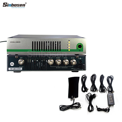
Sinbosen's Antenna Distributor system monitor is easier to carry and install.The active transmitter combiner is suitable for the Multi-channel monitoring systems for stage and Multi-channel wireless microphone antenna arrays for stage.
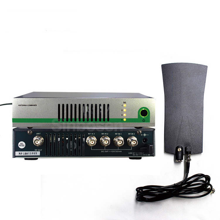
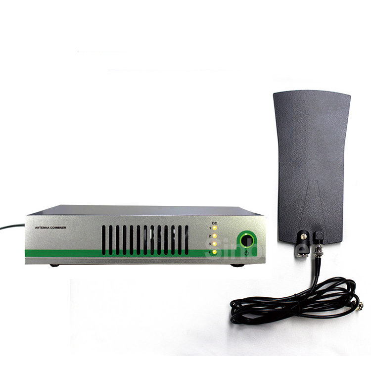
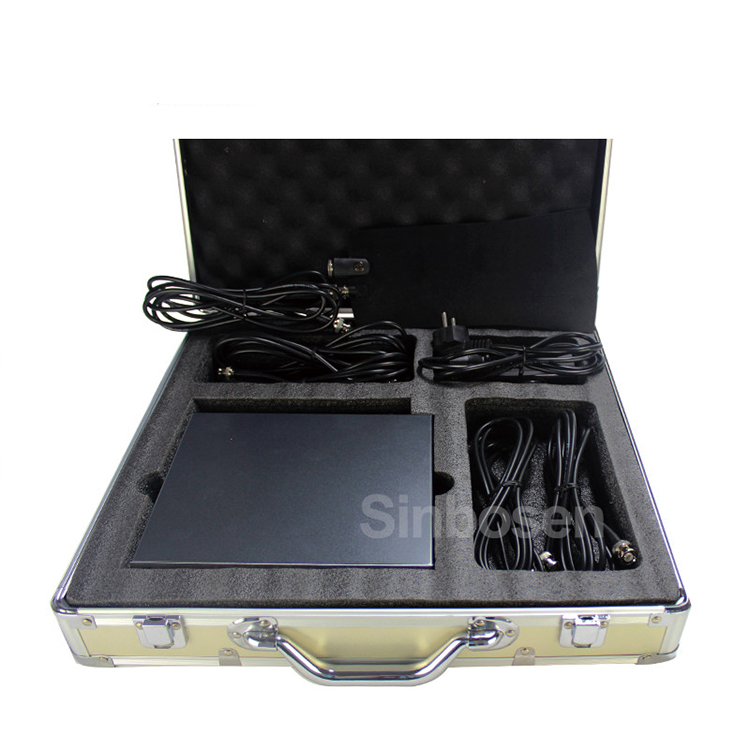
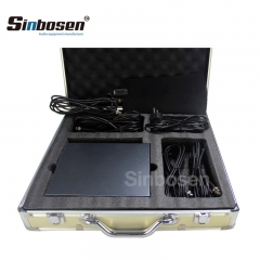
Package:
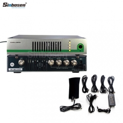
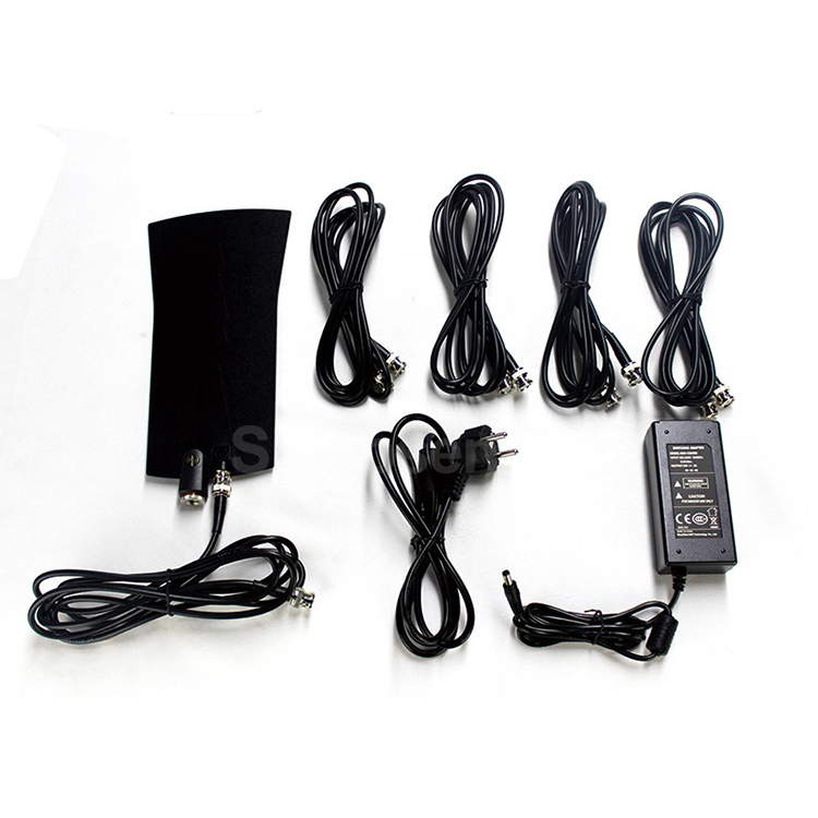
4 BNC cables
1 Power Supply
1 Operating instructions
1 AC-3 antenna combiner
1 Passive omnidirectional antenna
4 BNC cables
1 Power Supply
1 Operating instructions
1 AC-3 antenna combiner
1 Passive omnidirectional antenna
Feature:
►An Antenna Distribution System Wireless microphone.
►UHF antenna distribution system that allows the expansion of wireless microphone systems by splitting one pair of antennas to multiple receivers.
►Amplifies signals to compensate for insertion loss that results from splitting signal power to multiple outputs.
►An system can support up to eight wireless receivers.
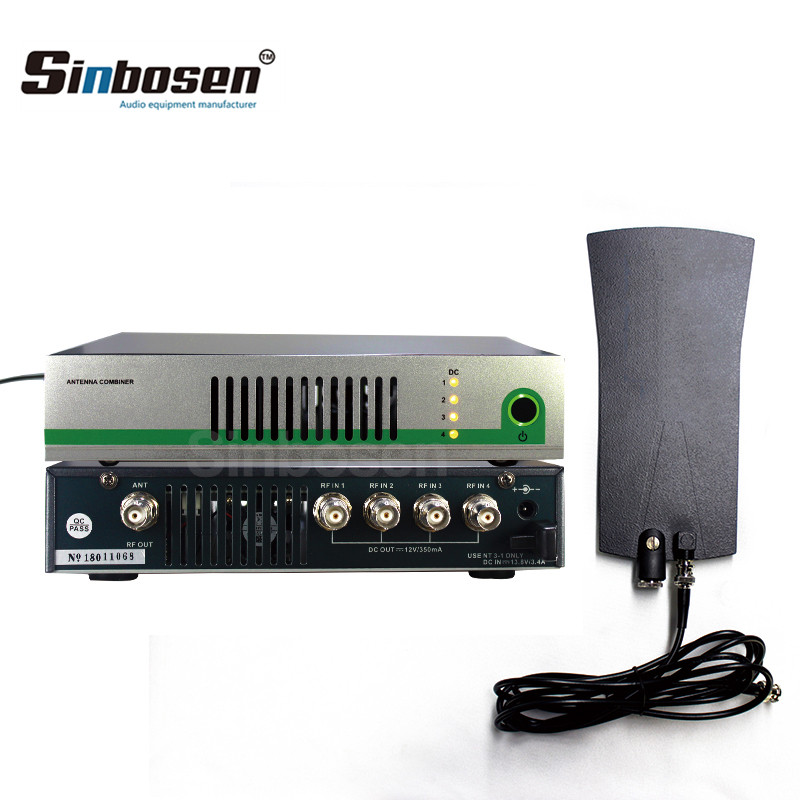
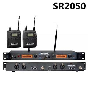
►With the active transmitter combiner, the signals of up to four type transmitters of wireless in ear monitor can be combined into a single antenna. Also can constitute the antenna arrays by connecting four antennas to ensure the antenna full precision coverage.
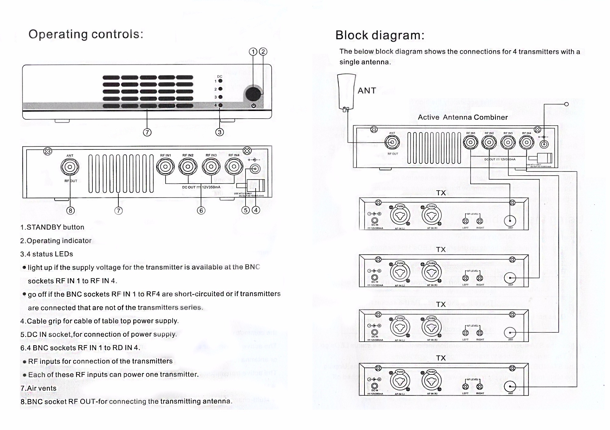
Operating controls
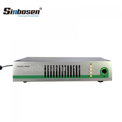
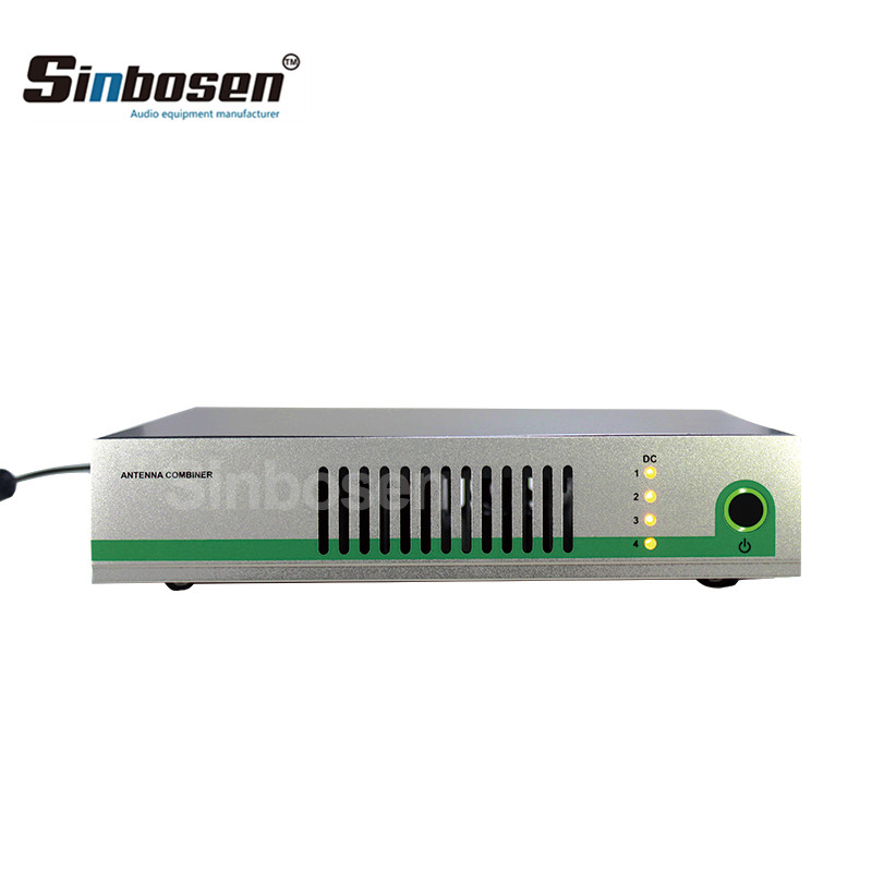
1.Standby button
2.Operating indicator
3.4 status LEDs
•Light up if the supply voltage for the transmitter is available at the BNC sockets RF IN1 to RF IN 4.
•Go off if the BNC sockets RF IN 1 to RF4 are short- circuited or if transmitters are connected that are not of the transmitters series.
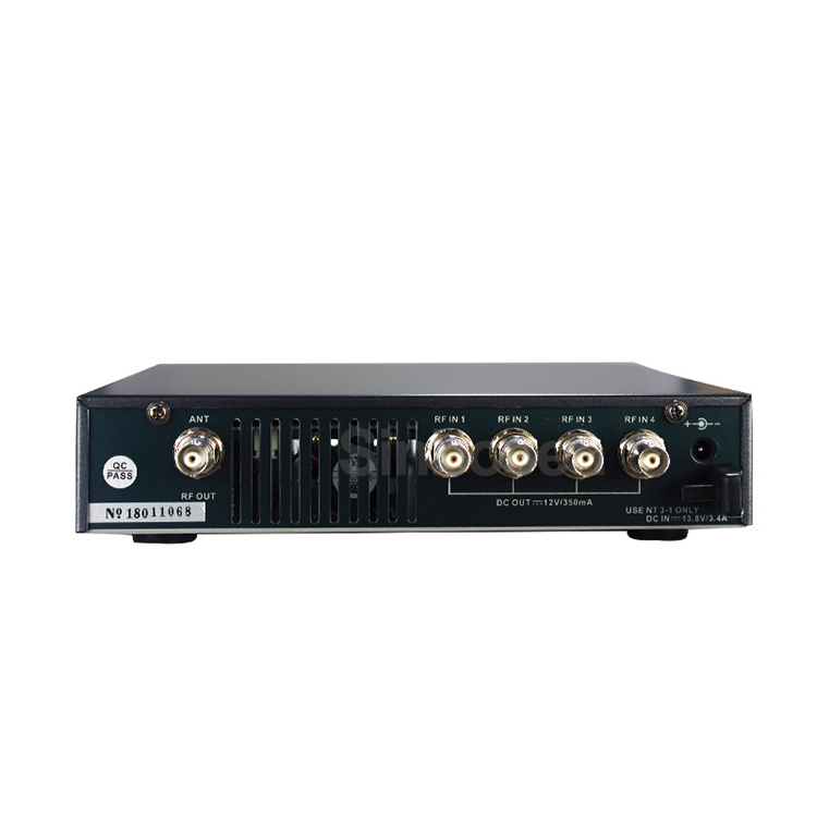
4.Cable grip for cable of table top power supply.
5.DC IN socket,for connection of power supply.
6.4 BNC sockets RF IN 1 to RD IN 4.
•RF inputs for connection of the transmitters.
•Each of these RF inputs can power one transmitter.
7.Air vents.
8.BNC socket RF OUT-for connecting the transmitting antenna.

 |
 |
 |
 |
 |
 |


