


How to set up the VPL of your amplifiers
Views : 19073
Update time : 2021-10-27 17:34:27
Part 1:Power amplifiers
Audio amplifiers increases a balanced line input signal to the sufficient level to drive the movement of a speaker cone.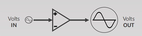
An amplifier is considered to have done its job successfully when the signal at the output is identical to the input signal but with higher amplitude.
Depending on the manufacturer we can find different features , some of them user configurable.

An amplifier is considered to have done its job successfully when the signal at the output is identical to the input signal but with higher amplitude.
Depending on the manufacturer we can find different features , some of them user configurable.
| Voltage Gain | Impendance | Sensors & Protections | Peak Power |
| •Gain dB | 2 ohms | • Temperature | Average Power |
| • Multiplier Factor | 4 ohms | • Open Load | THD% |
| • Sensitivity in Volts | 8 ohms/16 ohms | • Short Circuits | Damping |
Operation Mode |
Output Connectors | DSP | Factor |
| • Bridge | Consumption | Conectivity | Weight |
| • Paralell | Electrical | User interfase | Tech Support |
| • Stereo | Input Voltage |
Amplifier different types:
Due to their electronic manufacturing and the way they amplify the signal, they can be divided into
different types:
Class A - Class B - Class AB - Class C - Class H - Class D - Class TD

Power amplifier function:


Part 2:Harmonic Distortion

Part 3:Distortion Test


Part 4:Power Compression Phenomenon
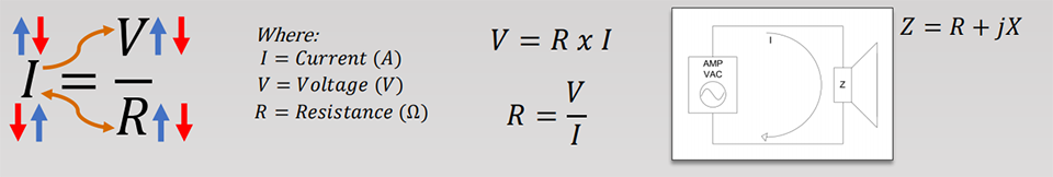
•OHM´S LAW
The current flowing thru a closed circuit, is directly proportional to the voltage and inversely proportional to the resistance in the circuit.
• ELECTRICAL POWER
The amount of energy delivered or absorbed by an element in a specific time. Voltage and current
flowing thru an electric circuit are directly proportional to the power:P=V*I
The amplifier delivers certain amount of power to the output and the impedance presented by the speaker generates the power

Peak power or instantaneous is what an amplifier is able to generate in a very short time with no damage.
It´s calculated based on the peak voltage or maximum amplitude of a signal.
Continuous power is the real or effective power that an amplifier is capable to generating for a long time.
It´s calculated based on the RMS voltage of a signal.

Part 5:Square Wave on different DB Crest Factor

Part 6:Switches Configuration

• Voltage Gain
Amplifier´s voltage gain is a voltage measurement at the output related to the input voltage, it determines the input signal required in volts to drive the amplifier to its maximum level at the output.
Due to the power depends on the load impedance, we usually take 4 ohms as reference.

• Gain Structure

• Voltage Gain Switches

• Output SpeakON Connectors

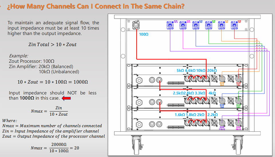
Part 7:How Many Channels Can I Connect In The Same Chain?
To maintain an adequate signal flow, theinput impedance must be at least 10 times higher than the output impedance.
• Bridge Mode
Bridge mode essentially place two channels in series to achieve more voltaje at the output in just one cannel bridged. In this way we doubles the voltage and is expected getting four times the power.

• Bridge Mode
Bridge mode essentially place two channels in series to achieve more voltaje at the output in just one cannel bridged. In this way we doubles the voltage and is expected getting four times the power.
| ADVANTAGES: | DISADVANTAGES: |
| • We double the voltage. | • Less amplifier channels available. |
| • We get four times the power. | • Increase in floor noise. |
| • Taking care about impedance it´s possible to connect more speakers in just one circuit. |
• Amplifiers impedance output is doubled. (Damping Factor is affected) |
| • The mínimum operating impedance must the double. |

• Bridge Mode Configuration Example

• Mode Switch

• VPL (Voltage Peak Limiter)
The VPL limits the maximum output voltage of the amplifier, it must be calculated based on the maximum power capacity of the speaker in order to don´t take the speaker beyond its mechanical capabilities.

• Series Speaker Wiring
Series connections are done when you wire speakers terminals successively, it increases the equivalent resistance of the circuit. An disadvantage can be that if one of the speakers fails, the current flow through the circuit it´s going to be interrupted.

• Parallel Speaker Wiring
They are made when the input speakers terminals converge at the same pole, likewise the output speakers terminals. So long as they are all the same impedance, the total impedance is equal to the impedance of one speaker divided by the total number of speakers.


• Series/Parallel Speakers Wiring
It´s is the combination of both series and parallel wiring in just one single circuit. To solve the total impedance,series circuits can be grouped first and then they solve like a single parallel circuit.


Part 7:Case Study


• Case Study – Switches Set Up

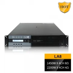
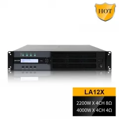
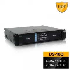
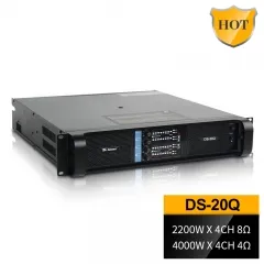
RELATED PRODUCT:
 |
 |
 |
 |
 |
Contact us:
Whatsapp:https://api.whatsapp.com/send?l=en&phnoe=8616676738225
Website:https://www.sinbosenaudio.com/

